DIY Smart Temperature Alerter
by Printerforge in Circuits > Electronics
277 Views, 4 Favorites, 0 Comments
DIY Smart Temperature Alerter

Cooking often demands precision, especially when temperature plays a crucial role in perfecting dishes like pasta, meats, or frying oil. Constantly watching and guessing can waste time and lead to mistakes. That’s where the Smart Temperature Alerter steps in—streamlining your cooking process by ensuring precision and eliminating guesswork.
This tool doesn’t just monitor temperature; it alerts you when your target is reached, allowing you to multitask with confidence. It tracks the current temperature and sounds an alarm when the ideal point is hit, whether you’re boiling water or preparing sous vide.
Here’s how it works: attach the thermistor, set your target temperature, and let the device handle the rest. With its simple interface and reliable alerts, the Smart Temperature Alerter transforms everyday cooking into an efficient and stress-free experience.
Supplies

Materials
- PETG (optional)
- PLA
- Glue (for securing components in place).
- Electrical tape or heat shrink tubing (for insulating exposed wires).
- M3x8 screws
Electronics
- Arduino Nano (microcontroller USB-C).
- TP4056 charger module (for battery charging USB-C).
- 18650 lithium-ion battery (for powering the device).
- LCD display (to show information).
- Speaker (for audible alerts).
- Rotary encoder with breakout board (recommended for easier wiring and reduced errors).
- Switch (for turning the device on and off).
- thermistor (for reading the temperature)
- Wires
- resistors
Tools
- Soldering iron (for soldering components).
- Allen wrench (for attaching the encoder and securing the lid).
- Wire cutters and strippers (for preparing wires).
- Hot glue gun or adhesive glue (for securing components).
- Multimeter (optional, for testing connections).
The Big Idea

The idea for the Smart Temperature Alerter came to life while I was boiling water—a task that’s deceptively simple yet requires constant attention. The thought struck me: wouldn’t it be great to know the exact temperature at any moment? Even better, what if there were an alarm to alert me when the water boils?
As I mulled it over, I realized just how central boiling is to cooking. From making pasta and simmering soups to poaching eggs, steaming vegetables, boiling potatoes, and preparing stews, so many recipes rely on precise temperature control. An alert system would not only simplify boiling but also offer a reliable reminder for these tasks.
This led me to design a device that could monitor the boiling point, provide real-time updates, and sound an alarm once the water hit its target. This approach allows me to multitask—working on other kitchen prep or projects—while still being aware of the process without hovering over the stove. You know what they say - “A watched pot never boils!” And boy is it boring to just stand there and watch.
What started as a simple convenience quickly evolved into a versatile tool with broader applications, all rooted in the need for efficiency and precision.
The Plan

Why Planning Matters
A well-structured plan is the backbone of any successful project. For the Smart Temperature Alerter, careful planning ensured the design stayed aligned with its core goals: affordability, reliability, and ease of use. By defining requirements early, I avoided feature creep and kept the project focused on practicality. Below, I’ll walk through the key decisions that shaped the device, from sensor selection to power management.
1. Defining Requirements
- Cost-Effective
- Prioritized generic components like Arduino-compatible microcontrollers, basic sensors, and 3D-printed parts to minimize expenses.
- Simple & Reliable
- Designed a straightforward circuit with minimal soldering and standardized parts for easy troubleshooting.
- User-Friendly
- Simplified controls to a single rotary encoder for setting temperature thresholds and muting alarms.
- Integrated color-coded LEDs and a buzzer for instant visual and auditory feedback.
- Portable
- Compact, battery-powered design with a detachable sensor for use in kitchens, workshops, or outdoors.
- Aesthetic
- Focused on a clean, modern look with a 3D-printed case to conceal wiring and highlight functional elements.

2. Thermistor Selection
The sensor needed to handle extreme temperatures, specifically boiling water (100°C/212°F), while resisting moisture. Most low-cost thermistors maxed out at 80°C, and waterproof versions often required bulky housings or proprietary connectors. After testing, I chose a 2-wire stainless steel thermistor rated for 125°C. Though its tolerance narrowed slightly at higher temperatures, this wasn’t an issue for boiling water applications, as open containers rarely exceed 100°C. The 2-pin design also added safety—if the sensor shorted, it would only connect ground-to-ground, preventing damage to the microcontroller.
3. Power Supply Design

Portability demanded a rechargeable power source. While AA or 9V batteries were initially considered, their non-rechargeable nature clashed with the goal of user-friendliness and long-term cost efficiency. The 18650 lithium-ion battery emerged as the ideal solution: compact, widely available, and capable of hours of runtime. To ensure safe charging, I paired it with a TP4056 module, which includes overcharge, over-discharge, and short-circuit protection. This setup eliminated the hassle of replacing disposable batteries while maintaining a sleek, self-contained design.
4. Display & User Interface


Clarity and simplicity drove the display choice. OLED screens offered crisp visuals but were deemed unnecessary for a device that only needed to show numeric temperatures. A 16x2 LCD, while less flashy, proved rugged, affordable, and easy to interface with Arduino libraries. For controls, a rotary encoder replaced traditional buttons. Its dual functionality (rotating to adjust temperatures and pressing to confirm/silence alarms) streamlined the interface, reducing clutter and coding complexity.

5. Alarm System Iteration
The ESP32-C3 SuperMini microcontroller was initially chosen for its compact size, Wi-Fi capabilities, and ample GPIO pins. Wi-Fi integration would have enabled smart features like Alexa alerts, but early testing revealed drawbacks. The ESP32’s power consumption strained the battery, and cloud-based alerts added firmware complexity. As a workaround, I incorporated a piezoelectric buzzer for local alarms—a loud, reliable solution that maintained the project’s focus on simplicity. While the ESP32 remains part of the current design, power efficiency challenges prompted a shift to a more streamlined microcontroller, which I’ll detail later.
6. Conclusion & Next Steps
This planning phase transformed abstract ideas into a functional blueprint. By balancing cost, usability, and aesthetics, the design avoids unnecessary complexity while remaining adaptable to future upgrades. In the next section, we’ll dive into circuit assembly, firmware programming, and 3D-printing the enclosure, bringing this temperature monitoring tool to life.
How This Works

How Thermistors Measure Temperature
A thermistor is a type of resistor whose electrical resistance changes with temperature. This feature allows it to function as a temperature sensor. Much like how heat affects the viscosity of a liquid—making it easier or harder to flow—temperature alters the resistance in a thermistor, controlling how much electricity can pass through it.

PTC vs. NTC Thermistors
Thermistors are categorized into two types:
- NTC (Negative Temperature Coefficient): Resistance decreases as the temperature increases, similar to how a snowman shrinks in the heat of the sun.
- PTC (Positive Temperature Coefficient): Resistance increases as the temperature rises, akin to a rubber band stiffening under heat, resisting further stretching.
This project uses a PTC thermistor, where resistance increases with temperature. This behavior ensures a predictable and intuitive relationship between temperature and resistance, making it easier to design a reliable circuit.
Using Resistance to Calculate Temperature
Initial Approach with Constant Mapping
In the project’s early stages, the temperature-reading code assumed a linear relationship between resistance and temperature. For instance:
- A resistance of 10kΩ was mapped to 25°C, while 20kΩ corresponded to 50°C.
- Similarly, voltage values like 0.1V=5°F and 0.2V=10°F were used for quick calculations.
However, this simplified method failed to account for the non-linear nature of thermistor behavior, leading to inaccuracies.

Understanding the Graph
When plotted, the resistance-temperature relationship for a PTC thermistor forms a curve, not a straight line. At lower temperatures, resistance changes gradually, while at higher temperatures (e.g., near boiling), resistance increases at an accelerated rate. This complex, non-linear relationship necessitated the use of the Steinhart-Hart equation for precise calculations.
The Steinhart-Hart Formula
The Steinhart-Hart equation is widely used for translating thermistor resistance into accurate temperature readings. It’s a mathematical tool that accounts for the non-linear behavior of thermistors by incorporating logarithmic transformations.

Where:
- T: Temperature in Kelvin.
- R: Resistance of the thermistor, measured in ohms.
- A,B,C: Calibration constants specific to the thermistor, derived from its datasheet.
Breaking Down the Formula
- Calibration: Using resistance-temperature pairs from the thermistor’s datasheet, the constants A,B, and C are determined. These constants define the thermistor’s unique response curve.
- Logarithm of Resistance (lnR): This logarithmic transformation adjusts for rapid resistance changes at specific temperature ranges, simplifying the complex curve into something calculable.
- Cubic Term: The term (lnR)3 fine-tunes the model, ensuring accuracy across a wide range of temperatures.
By integrating this formula into the code, the system dynamically reads resistance, applies the Steinhart-Hart equation, and outputs temperatures in both Celsius and Fahrenheit with high accuracy.
Electricity in the Circuit
In this system, electricity operates much like water flowing through pipes:
- Voltage (V): Acts like water pressure, pushing electrons through the circuit.
- Current (I): Represents the flow rate of electrons.
- Resistance (R): Is like a narrow pipe restricting flow.
The relationship between these elements is defined by Ohm's Law:
V=I⋅R
This foundational principle underpins the entire circuit, allowing precise control over how electricity interacts with the thermistor and other components.
Why Use an 18650 Battery?

18650 lithium-ion batteries are favored in DIY electronics due to their:
- Rechargeability: Avoids constant replacement, aligning with sustainable practices.
- High Capacity: A typical capacity of ~3000mAh ensures hours of uninterrupted operation.
- Compactness: Their cylindrical shape fits neatly into 3D-printed compartments, maintaining portability without compromising performance.
TP4056: The Battery Guardian

The TP4056 module is a dedicated charging and protection circuit for lithium-ion batteries. It provides:
- Safe Charging: Prevents overcharging, which can damage or overheat the battery.
- Discharge Protection: Automatically cuts off power to prevent over-draining, preserving battery health.
- Short-Circuit Prevention: Acts as a failsafe against wiring errors, protecting both the circuit and the user.
This module simplifies battery management, making it an essential component in portable designs.
LCD
LCD (Liquid Crystal Display)

- Functionality: Liquid crystals control the passage of light from a backlight, forming characters on the display.
- Advantages: Durable, cost-effective, and ideal for displaying basic numeric data.
- Why It’s Used: Its rugged nature and affordability make it perfect for this application.
- Why I2C

The I2C protocol reduces wiring complexity by allowing multiple components to communicate over just two lines—SDA (data) and SCL (clock). This approach minimizes clutter compared to traditional pin-per-device setups, which would require separate connections for each component. For our case this converts 16 pins to wire to only 4 pins to wire. (SDA, SCL, VCC, GND).

How a Rotary Encoder Works

A rotary encoder translates rotational motion into digital signals:
- Turning the Knob: Generates pulses that indicate direction and number of steps.
- Pressing the Knob: Acts as a button, adding versatility to its functionality.
This dual-purpose component simplifies user input by consolidating multiple control actions into a single interface.
Piezoelectric Buzzer Operation

An active piezoelectric buzzer creates sound through the vibration of a ceramic crystal. When voltage is applied, the crystal rapidly expands and contracts, producing sound waves. This mechanism makes the buzzer efficient, reliable, and loud enough to function as an effective alert system.
Errors with Alexa Integration

Using IFTTT
The initial idea was to use the ESP32 to trigger Alexa alarms via IFTTT (If This Then That). This service connects devices and apps through automation rules called applets:
- Trigger: The ESP32 detects a boiling point and sends a signal to IFTTT.
- Action: Alexa announces, "Your water is boiling."
However, implementing IFTTT revealed several drawbacks:
- Costs: Advanced features required a subscription, conflicting with the project’s cost-effective goals.
- Setup Complexity: Integrating the ESP32, IFTTT, and Alexa involved multiple layers, increasing the potential for errors.
- Internet Dependency: As a cloud-based service, IFTTT was susceptible to latency and outages.
Why I Chose Not to Use IFTTT
The main reason for abandoning IFTTT was its subscription cost. Many of its advanced features—needed for a seamless integration—were locked behind a paywall, conflicting with the project’s goal of being cost-effective and accessible.
Additionally, IFTTT’s reliance on internet connectivity introduced issues of latency and outages. While these weren’t dealbreakers on their own, they added an unnecessary layer of unpredictability to a system meant to be reliable.
Switching to Arduino Nano
Given these limitations, I chose to simplify the design by replacing the ESP32 with an Arduino Nano. There was no need for Wi-Fi or Bluetooth capabilities, as the project didn’t require wireless communication. With space available in the device and no need for connectivity features, the ESP32’s extra capabilities became redundant.
The Arduino Nano turned out to be the perfect fit:
- Cost-Effective: More affordable than the ESP32, aligning with the project’s budget-conscious goals.
- User-Friendly: Seamless compatibility with peripherals like I2C and simplified coding processes.
- Simplicity: By eliminating unnecessary features, the Nano streamlined the design without sacrificing functionality.
This transition not only reduced complexity but also ensured a reliable, efficient, and cost-effective solution for the Smart Temperature Alerter, removing the dependency on internet-based tools entirely.
Modeling

Basic Overall Design Constraints:
Before starting, we established the constraints for the design:
- Cost-Effective: Use affordable components like generic Arduino boards, thermistors, and 3D-printed parts to keep the project budget-friendly.
- Simple and Reliable: Ensure accurate temperature readings with a straightforward circuit and easily replaceable standard components.
- User-Friendly Interaction: Intuitive, one-button operation supported by color-coded LEDs and a loud buzzer.
- Portable: Compact design with a detachable sensor and rechargeable battery for ease of use anywhere.
- Aesthetic: A sleek, customizable 3D-printed case with subtle LED accents for a polished, modern look.
Now, the design work began:
Step 1: Creating the Sketch
I began the design process by sketching the base outline of the model. The dimensions for the main rectangle were 100mm by 150mm, providing ample space for the components while maintaining a compact form factor. To add a touch of uniqueness, I incorporated a small arch at the bottom of the rectangle.

Key Aspects:
- Base Dimensions:
- The 100mm x 150mm size ensures a balanced and manageable enclosure, supporting the Portableconstraint.
- The spacious yet compact design comfortably houses critical components, including the Arduino Nano, thermistor, and battery.
- Arch Design:
- The arch at the bottom enhances the Aesthetic constraint by adding a sleek, modern touch.
- It also provides flexibility for future design elements like cable routing or mounting points.
Step 2: Extruding the Sketch and Adding Fillets
Next, I extruded the sketch to create the main body of the enclosure and added fillets to the edges. The extrusion gave the model its 3D shape, while the fillets softened sharp edges for a modern aesthetic.

Key Aspects:
- Extrusion for the Main Body:
- The base rectangle with its arched bottom was extruded upwards to form the enclosure's primary structure.
- This serves as the foundation for the entire design.
- Fillets for Modern Appeal:
- Smooth, rounded transitions were added to all edges, enhancing comfort and usability.
- This step aligns with the Aesthetic constraint by achieving a professional, polished appearance.
Step 3: Importing Components from GrabCAD
To ensure accurate dimensions and proper placement, I imported pre-designed components from GrabCAD. These real-world electronic modules provided a precise guide for scaling and alignment.

Key Aspects:
- Finding Components on GrabCAD:
- I accessed GrabCAD’s extensive library for essential modules like the Arduino Nano and TP4056.
- These files are precise and contributed to accurate modeling.
- Simulating, Not Printing:
- The components are not part of the 3D-printed enclosure but were used as reference models for dimensioning.
- By simulating the real-world parts, I ensured snug fits and minimized design iterations.
- Improved Accuracy:
- GrabCAD’s high-detail files saved time, ensuring all placements adhered to the Compact Size and Simple and Reliable constraints.
Step 4: Hollowing Out the Main Body
Using the shell command, I hollowed the main body to prepare for housing the electronics. I maintained a 3mm wall thickness for strength and interior space balance.

Key Aspects:
- Hollowing with the Shell Command:
- This step removed material from inside the enclosure, creating space for critical components like the Arduino Nano, thermistor, and wiring.
- 3mm Wall Thickness:
- A consistent 3mm thickness ensures durability while maximizing the internal workspace.
- This approach fulfills the Simple and Reliable constraint.
- Component Readiness:
- The hollowed design simplifies placing and securing components during assembly.
Step 5: Simplifying the TP4056 Model
This step illustrates an important example of working with GrabCAD models. When importing the TP4056 module from GrabCAD, the file contained over 1,000 individual bodies, as each electronic component (resistors, capacitors, ICs, etc.) was modeled separately. While this is an impressive level of detail, it was unnecessary for my design purposes, as I only required the outer rectangle dimensions to properly fit the component into the enclosure.

Key Aspects:
- GrabCAD’s High-Level Detail:
- GrabCAD provides highly detailed and accurate models, which is fantastic for visualizing or analyzing every tiny component of a design. However, in cases like this, such an excess of details can make the imported files cumbersome, increasing file size and slowing down the CAD software.
- This scenario demonstrates how GrabCAD models, while useful, may need simplification depending on the purpose.
- Adapting the Model:
- To resolve this, I created a simplified version of the TP4056 by focusing only on the critical outer dimensions. Using the bottom face of the module, I extruded it to create a single-body representation. This method replaced the original model with one that achieved the same fitting purpose but was far less complex.
- Efficiency Gained:
- By simplifying the TP4056 into a single-body object, I maintained the accuracy of its placement while significantly optimizing the CAD workflow. This process saved time and made the design file lighter and more manageable.
- Lesson from GrabCAD:
- The TP4056 module showcases how GrabCAD’s extensive library provides powerful tools for prototyping and simulation. Still, not every design needs intricate detail—sometimes a straightforward, custom-made approximation is more efficient and practical.
Step 6: Placing the TP4056 in Its New Location
After simplifying the TP4056 model, I proceeded to move it to its designated location within the main body of the enclosure. This step was critical to ensuring the module fits securely and aligns properly with other components.

Key Aspects:
- Precise Placement:
- The TP4056 was positioned on a flat surface inside the enclosure. Its location was chosen strategically to allow proper wire routing to both the battery and the external connection points, ensuring efficient use of space and minimal interference with other components.
- Alignment and Fit:
- The simplified TP4056 model was partially inserted into a slot or recess designed for it. This ensures the module remains stable and secure during operation, reducing the chance of displacement due to vibrations or handling.
- By verifying the alignment within the enclosure, I ensured that the module does not obstruct or interfere with other critical elements, like the LCD display at the top or the thermistor exit at the bottom.
- Maintaining Accessibility:
- Care was taken to leave access to the module’s connectors, allowing for straightforward wiring and future maintenance. This approach supports the User-Friendly Interaction and Simple and Reliable constraints.
- Optimizing the Workspace:
- The surrounding area, represented by the grid pattern in the modeling environment, provided a clear reference plane for adjustments. This step helped ensure the TP4056 was integrated smoothly and proportionately into the overall layout.
Step 7: Extruding a Hole for the USB-C Port
Next, I extruded a hole in the enclosure to accommodate the USB-C connector. This port ensures that the module can be plugged in and out easily. To achieve this, I provided generous tolerance around the USB-C dimensions, prioritizing accessibility over a waterproof seal.

Key Aspects:
- Creating the USB-C Hole:
- The hole was carefully extruded to match the dimensions of the USB-C connector, ensuring it fits snugly but with enough space for smooth insertion and removal.
- Providing Generous Tolerance:
- Tolerance was intentionally increased to prevent any difficulty when connecting or disconnecting the USB-C cable. This design choice ensures a user-friendly experience, adhering to the User-Friendly Interactionconstraint.
- The focus was on making the port highly functional, as waterproofing was not a primary concern for this design.
- Ensuring Easy Alignment:
- The placement of the hole was chosen to align perfectly with the USB-C port on the TP4056 module, ensuring that the connector slides in without obstruction or the need for adjustments.
Step 8: Adding the Microcontroller and USB-C Port
Initially, I imported an ESP32 into the design and prepared the model to fit it. While the design was tailored around the ESP32, I eventually decided to switch to using an Arduino Nano although I didn’t know that at this time.
I started by positioning the ESP32 in its intended location, taking care to align it for efficient wiring and easy access to its ports. To accommodate the ESP32's USB-C port, I extruded a hole in the enclosure, adding generous tolerance to ensure smooth operation.

Key Aspects:
- Positioning the ESP32:
- The ESP32 was placed near the center of the enclosure to allow efficient routing of wires to other components while maintaining balance and usability.
- Extruding the USB-C Port Hole:
- A hole was extruded to match the USB-C connector on the ESP32. Generous tolerance was added around the edges to ensure smooth insertion and removal of the USB-C cable without any obstructions.
- Since waterproofing was not a primary concern for this design, the focus was on accessibility and ease of use, aligning with the User-Friendly Interaction constraint.
- Preparing for Later Adjustments:
- Even though I eventually transitioned to an Arduino Nano, designing around the ESP32 was a crucial step in understanding how to adapt the enclosure for different components. The design workflow ensured that future changes could be implemented seamlessly.
Step 9: Extruding the Top Section of the Enclosure
To finalize the overall structure of the enclosure, I extruded the top section. This addition serves several crucial purposes, from functionality to visual cohesion, completing the encasing of the internal electronics while maintaining the sleek aesthetic.

Key Aspects:
- Housing Additional Electronics:
- The extruded top provides the necessary space to integrate key components, such as the encoder, LCD display, speakers, and switch. Each element will be securely mounted within this section, ensuring proper functionality.
- Encasing the Design:
- By extending the enclosure upwards, I fully encapsulated all internal components. This approach protects the electronics from external damage while maintaining a clean and professional appearance, adhering to the Aesthetic constraint.
- Aesthetic Alignment:
- The top section was designed to seamlessly flow with the main body, preserving the smooth edges and modern design language established earlier. This ensures the enclosure remains visually appealing from all angles.
- Balanced Height and Functionality:
- The height of the extrusion was chosen carefully to accommodate the components without making the enclosure bulky. This decision supports the Portable and User-Friendly Interaction constraints, ensuring the final device remains compact and easy to handle.
Step 10: Sketching the LCD Display
To integrate the LCD display, I began by sketching its outline on the top section of the enclosure. The GrabCAD LCD model proved invaluable during this step, as it allowed me to simulate the correct size and ensure everything fit together seamlessly. While I didn’t rely on the exact dimensions of the GrabCAD model due to the need for tolerance, it served as an excellent reference for accuracy.

Key Aspects:
- Referencing the GrabCAD Model:
- The dimensions of the GrabCAD LCD model helped me visualize the size and placement of the display.
- Using this reference, I was able to ensure that the sketch aligned with the overall design, fitting the enclosure without crowding other components.
- Adjusting for Tolerance:
- Rather than directly using the GrabCAD model, I incorporated tolerance into my sketch. This ensures the LCD fits snugly into the slot without being too tight or difficult to install.
- The added flexibility supports a user-friendly assembly process and avoids potential damage during installation.
- Establishing the Placement:
- The LCD display is positioned on the top section of the enclosure, ensuring it remains prominent and easily readable. This placement aligns with the User-Friendly Interaction constraint by prioritizing visibility and accessibility.
Step 10 (Part 1): Creating the Negative Volume for the LCD Display
In this step, I made several critical extrusions to form what’s called a negative volume for the LCD display. Instead of directly representing the LCD's shape, this extrusion models the space that will hold the LCD. Essentially, this is the precise size of the LCD screen, and it helps to ensure a snug fit within the enclosure.

Key Aspects:
- Purpose of the Negative Volume:
- The negative volume represents the exact shape and size of the LCD. By extruding this, I created a placeholder that ensures the actual LCD will fit seamlessly into the enclosure.
- This method is especially helpful in verifying measurements and tolerances to avoid any fitting issues during assembly.
- Simulating Fit:
- By extruding the negative volume, I could visualize how the LCD display interacts with the rest of the design. This approach eliminates guesswork, as I can confirm that the size and positioning are correct before finalizing the cut.
- Prepare for the Combine Tool:
- The next step will involve using the combine tool to subtract this negative volume from the top section of the enclosure. This process will create a slot perfectly sized for the LCD to sit securely in place.
- The use of the combine tool ensures precision and keeps the final design aligned with the User-Friendly Interaction and Aesthetic constraints.
Step 10 (Part 2): Visualizing How the LCD Fits Inside the Body
For this step, I set the opacity of the enclosure to 50% to help illustrate how the LCD display fits snugly within the body. The negative volume created earlier accurately represents the space needed to securely hold the LCD, even without including every intricate detail of the model.


Key Points for the Reader:
- Replicating the LCD Shape:
- The negative volume within the enclosure is a simplified representation of the LCD's exact dimensions. It ensures that the enclosure will hold the LCD securely in place while keeping the design straightforward.
- Purpose of Transparency:
- The semi-transparent view demonstrates how the LCD will fit into the negative volume. This provides visual confirmation that the dimensions and tolerances are correct, ensuring a snug but accessible fit.
- Holding the LCD in Place:
- The body serves as a slot to securely hold the LCD in position during use, keeping it stable and aligned with the enclosure's design.
- Why Intricate Detail Isn’t Needed:
- The model of the LCD only needs its outer dimensions to create a functional holder. Internal details like circuitry or mounting holes are unnecessary, as the goal is simply to fit the LCD in place within the enclosure. This simplification ensures the design process is efficient while meeting functional requirements.
Step 10 (Part 3): Using the Combine Tool and Cut Function to Create the LCD Holder
In this step, I used the combine tool with the cut function to finalize the LCD holder within the enclosure. This process involved subtracting the negative volume created earlier from the body of the enclosure, leaving behind a slot that matches the dimensions of the LCD perfectly.

Key Aspects of the Process:
- How the Combine Tool Works:
- The combine tool allows you to merge, subtract, or intersect two or more bodies. In this case, I used it to subtract the negative volume of the LCD from the enclosure’s top section.
- The Cut Function Explained:
- The cut function specifically removes the volume of one body from another. By selecting the negative volume of the LCD as the cutting tool, the material was removed from the enclosure in exactly the shape of the negative volume.
- This approach ensures precision, as the resulting slot matches the LCD's dimensions with the tolerance I had built into the negative volume.
- Final Result:
- The cut created a perfect holder for the LCD display. It accurately mirrors the size and position of the negative volume, ensuring the LCD fits snugly and securely.
- The combination of the negative volume and the cut process eliminates guesswork, producing a professional and reliable fit for the display.
- Why It’s Effective:
- This method leverages the accuracy of 3D modeling to ensure the LCD slot is functional and holds the display properly. The use of the negative volume guarantees that the outer dimensions of the LCD are accounted for, making assembly simple and ensuring that the display stays in place during operation.
Step 11: Designing the Removable Lid for Electronics Access
The next phase of the design focused on creating the lid, which is a separate part of the enclosure's top section. This lid plays a crucial role as it provides access to the internal electronics, making it easier to perform modifications, repairs, or upgrades in the future.

Key Details:
- Purpose of the Lid:
- The lid acts as a protective cover for the electronics while allowing straightforward access when needed. This design ensures that the components inside, such as the Arduino Nano, LCD display, and other modules, can be easily reached.
- Separate Part for Accessibility:
- By designing the lid as a detachable component, I ensured that it could be removed independently without affecting the rest of the enclosure. This approach makes the device user-friendly, supporting quick and hassle-free access to the internals.
- Fitting Design:
- The lid was modeled to fit perfectly onto the enclosure's main body, with smooth edges and tolerances that hold it securely in place while still being easy to remove. This ensures the Aesthetic and Simple and Reliable constraints are upheld.
- Enhanced Functionality:
- With this removable design, the lid provides a convenient solution for maintaining and modifying the device. Whether replacing components, adjusting wiring, or upgrading the system, the lid simplifies the process.
Step 12: Adding Components to the Lid
The lid was designed to house three key electronic components: two buzzers and an encoder. The placement and distribution of these components were carefully thought out to maximize both functionality and aesthetic appeal.

Key Aspects of the Design:
- Buzzer Placement:
- Two buzzers were positioned symmetrically on the left and right sides of the lid. This layout was chosen to enhance the sound output by distributing the noise evenly.
- The symmetry also contributes to a visually balanced and cohesive design, aligning with the Aestheticconstraint.
- Encoder in the Center:
- The encoder was placed in the middle of the lid. This central positioning ensures ergonomic usability, as the encoder is easily accessible for interacting with the system.
- Design Intent:
- The dual buzzers were selected to amplify noise output, making the alerts clearer and louder. The specific left and right placement emphasizes the modern and sleek aesthetic while maintaining functionality.
- By concentrating all three components on the lid, the enclosure ensures efficient space utilization and simplifies maintenance, as accessing these components only requires removing the lid.
- Simplified Access:
- Since the lid is removable, this design choice also ensures that any fixes, adjustments, or modifications to the buzzers or encoder can be done quickly without having to disassemble the rest of the enclosure.
Step 13: Sketching and Extruding the Holder for the Three Electronics
To prepare for mounting the two buzzers and the encoder, I created a detailed sketch and then extruded it to form physical holders within the lid. This process ensures each component has a secure and precise mounting location while maintaining accessibility and aesthetics.


Key Aspects:
- Encoder Mounting:
- The encoder was designed to be held securely by screwing it in through its shaft. This approach ensures stability during operation while allowing for easy installation or removal when needed.
- Component Alignment:
- The two buzzers were placed symmetrically on the left and right sides of the lid, while the encoder was positioned in the center. This layout enhances functional stability and delivers a visually pleasing, balanced design.
- Purpose of the Sketch:
- The sketch served as a blueprint for allocating precise slots for each component. This ensures the electronics are securely mounted while remaining accessible for any future adjustments or repairs.
- Extrusion for Physical Holders:
- After completing the sketch, I extruded the features to create tangible slots for the components. These extrusions transformed the 2D layout into a 3D structure, ensuring that each electronic part fits snugly and at the correct depth within the lid.
- The extrusion also provides a clear visual of how the buzzers and encoder integrate with the overall lid design, showcasing their exact placement and alignment.
Step 14: Adding Bottom Notches to Support the Lid/Cover
To ensure the lid remains secure and stable, I added notches at the bottom section of the enclosure. These notches serve two important purposes: preventing the lid from collapsing inward and providing screw holes to fasten the lid in place. Their placement in the four corners allows maximum stability while leaving open space in between for ease of access and design efficiency.

Key Aspects:
- Purpose of the Notches:
- Structural Support: The notches prevent the lid from collapsing inward under pressure, maintaining its shape and structural integrity.
- Screw Mounting: Each notch includes a hole or slot designed to accommodate screws. This ensures the lid can be securely fastened to the enclosure, holding it firmly in place during use.
- Placement in the Corners:
- By positioning the notches in the four corners, the lid gains stable support at critical points, preventing wobbling or misalignment.
- The open space in between the notches allows for better accessibility to the electronics inside while maintaining an efficient design that avoids unnecessary material usage.
- Seamless Integration:
- The notches were carefully designed to blend with the enclosure's aesthetic, maintaining the sleek and modern appearance of the overall design.
Step 15: Adding a Slot Hole for the Thermistor Cords
The next step involved creating a slot hole on the enclosure to allow the thermistor cords to pass from the microcontroller inside to the outside, while maintaining the sleek aesthetic of the design.

Key Aspects:
- Purpose of the Slot Hole:
- The slot hole provides a clean and functional pathway for the thermistor cords to exit the enclosure, ensuring proper connectivity without disrupting the enclosure’s streamlined appearance.
- Aesthetic Consideration:
- The slot was designed to blend seamlessly with the enclosure, maintaining the modern and cohesive look of the overall device. Its positioning was carefully chosen to avoid clutter and maintain symmetry.
- Ensuring Functionality:
- The size of the slot was adjusted to accommodate the thermistor cords comfortably, without being excessively large or intrusive. This ensures both aesthetic appeal and ease of use during assembly.
- Integration with Design:
- The slot hole aligns with the layout of the internal electronics, providing a direct and unobstructed route for the thermistor cords to connect externally. This keeps the wiring organized and prevents tangling or interference with other components inside.

Designing a Probe Holder
One critical challenge in the Smart Temperature Alerter project was securely holding the thermistor probe in place. While the metal tip of the probe is designed to withstand high temperatures, the attached wire is less heat-resistant and requires protection from direct exposure to hot surfaces. This led to the exploration of different probe-holding mechanisms, with iterative improvements based on testing and practicality. Here’s the journey through the design process:
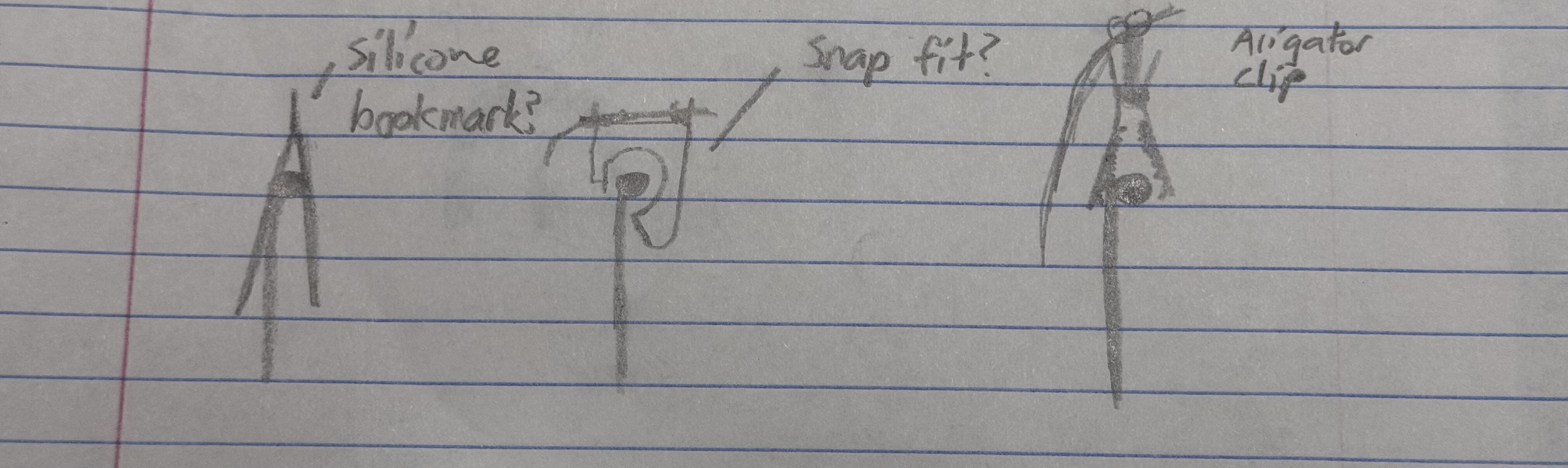
Initial Idea: Silicone Bookmark
- Concept: The first design involved using a silicone piece shaped like a bookmark to hold the probe. Silicone was chosen for its heat-resistant properties and flexibility.
- Testing: While silicone performed well in resisting heat, the design failed to secure the probe properly. During tests, it slipped out frequently, especially when the wire moved slightly. The lack of grip rendered this idea unreliable for consistent use.
- Conclusion: Silicone as a bookmark-style holder couldn’t provide the necessary stability.
Second Idea: 3D-Printed Snap Fit
- Concept: The next iteration used a snap-fit design made from 3D-printed materials like PLA and PETG. This concept aimed to clip onto the pot while holding the probe securely.
- Testing: While the snap-fit design offered better stability than the silicone bookmark, it introduced a new problem—material softness at high temperatures. Both PLA and PETG soften or deform at temperatures near or exceeding 100°C, which is common for a boiling pot.
- Conclusion: The reliance on heat-sensitive materials made this design unsuitable for practical use in high-temperature environments.
Third Idea: Alligator Clip
- Concept: The third approach used an alligator clip to grasp the probe. The metal clip promised a strong, secure grip and heat resistance.
- Testing: The clip held the probe well, but its metal teeth raised concerns about scratching or damaging the pot’s surface during use. Protecting the cookware was essential for maintaining usability and safety.
- Conclusion: Despite its strength, the risk of damage to pots from the clip’s teeth limited its practicality.
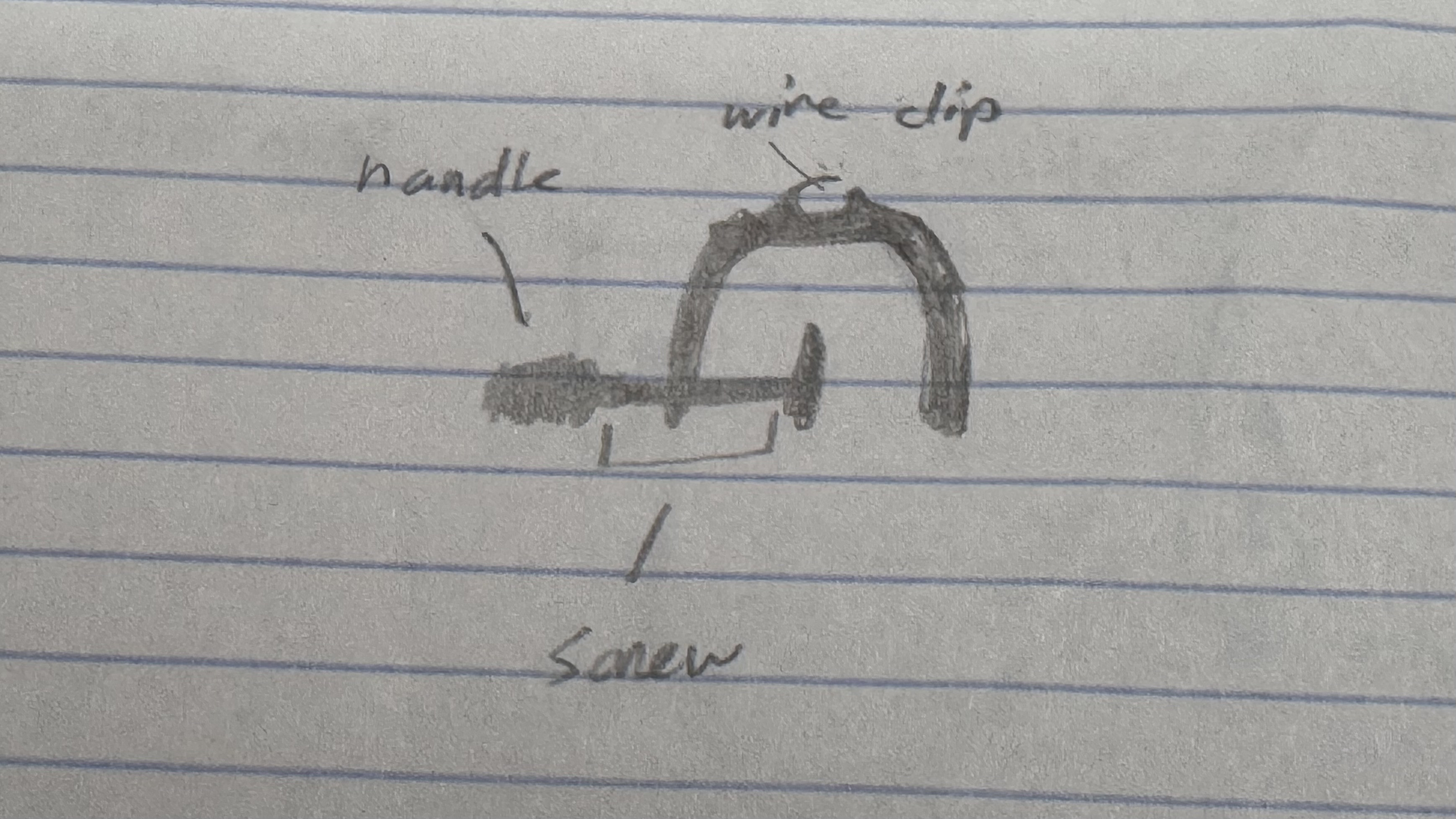
The Breakthrough: Leveraging the Handle
- Inspiration: While cooking, the pot handle provided a moment of clarity. Unlike the pot itself, the handle stays cooler and offers a sturdy mounting point. This observation shifted the focus from clamping onto the pot’s body to utilizing the handle instead.
- Solution Exploration: Two concepts emerged:
- Vice Grip: A vice-like mechanism could securely attach to the handle while holding the probe in place. However, this idea felt too bulky for the design.
- Clamp: The final idea was a clamp designed to attach to the handle. Clamps are lightweight, easy to use, and provide a non-damaging way to secure the probe without risking heat exposure to the wire.
Modeling the C-Clamp:
Step 1 – Creating the Sketch for the C-Clamp
For this phase, I began by sketching the initial outline for the C-clamp. While the sketch doesn’t resemble a C-clamp just yet, this is the foundational step where I started mapping out key features. The circle you see in the lower section of the rectangle will eventually serve as the slot for the screw mechanism, a critical part of the clamp’s functionality.

Key Aspects of the Sketch:
- Foundational Layout:
- The overall structure includes a large rectangle divided into two sections, providing the base dimensions for the C-clamp.
- This sketch will evolve into the final shape as features are added and refined.
- Screw Placement:
- The circle in the lower section is precisely positioned to represent where the screw mechanism will be installed. This placement ensures proper alignment for the screw to exert even pressure during operation.
- Initial Design Approach:
- Though the sketch is simple at this stage, it sets the stage for the rest of the design. The constraints from the original project, like ensuring a cost-effective, simple, and aesthetic design, remain central to this phase.
Step 2: Extruding the Sketch
I extruded the initial sketch to begin shaping the C-clamp. The top rectangle from the sketch was extended to form the top section of the clamp, which will provide the necessary compression force. Additionally, the circular hole at the bottom was preserved during the extrusion process, creating the slot where the screw mechanism will later be installed.

Key Aspects:
- Forming the Top of the C-Clamp:
- The top section was shaped through extrusion, establishing the main surface that will apply downward pressure when the clamp is in use.
- Preserving the Screw Hole:
- The circular hole from the sketch was included in the extrusion, forming a clean and precise opening for the screw mechanism. This feature is critical for the clamp's function.
Step 3: Mirroring the Sketch and Modifying Features
I mirrored the initial sketch to create the opposite side of the C-clamp, ensuring symmetry. After mirroring, I removed the hole on the other side to refine the design and prepare for the next step. This adjustment keeps the layout clean while maintaining structural balance.

Step 4: Creating the Screw and Handle
I designed two cylinders to form the screw assembly for the C-clamp. The first cylinder represents the actual screw, which will thread through the circular opening in the clamp body. The second, wider cylinder forms the screw top or grip, allowing the screw to be tightened manually.

Key Aspects:
- Screw Cylinder:
- A narrow cylinder was created to act as the screw itself. This component ensures smooth threading and provides the necessary force during operation.
- Handle Cylinder:
- A wider cylinder was added to the top of the screw to serve as the grip or handle. This allows for easy manual operation and ensures sufficient torque can be applied.
- Integration:
- The screw and handle were combined seamlessly, ensuring the assembly aligns perfectly with the clamp’s design constraints for User-Friendly Interaction and Cost-Effective construction.
Step 5: Creating the Grip
- Part 1: Using the Coil Tool
- I started by using the coil tool to make the initial spiral cut into the screw handle. This first coil established the foundation for the grip's design, creating a textured surface that would later be expanded for improved functionality and aesthetics.

- Part 2: Patterning and Mirroring the Design
- After creating the initial spiral cut, I applied a patterning and mirroring technique to extend the design across the entire surface of the screw handle. This ensured the texture covered the handle evenly, creating a seamless design that is both visually appealing and practical.

- Part 3: Finalizing the Criss-Cross Pattern
- The combined effect of patterning and mirroring resulted in a refined criss-cross texture on the screw handle. This intricate pattern enhances the grip by providing excellent traction while adding a modern and stylish detail to the overall design. The criss-cross grip aligns perfectly with the User-Friendly Interaction and Aesthetic constraints, ensuring both functionality and elegance.

Step 6: Modeling the Screw
I began by modeling the screw to ensure it would function properly in the C-clamp while being suitable for 3D printing. I opted for a thicker screw with an appropriate pitch, ensuring it could be printed effectively without compromising strength or functionality. The thicker design ensures durability during use, while the pitch allows for smooth threading and reliable performance in the clamp mechanism. This step focuses on both practicality and manufacturability.

Step 7: Filleting the C-Clamp
To elevate the design and add a polished touch, I applied fillets to the edges of the C-clamp. This step was vital in transforming the raw extruded model into a more refined and visually appealing design. By rounding the sharp corners and transitions, the fillets not only enhanced the aesthetics but also contributed to the overall usability and durability of the clamp.

Key Aspects:
- Aesthetic Transformation:
- The addition of fillets smoothed out the harsh edges, giving the clamp a sleek and modern appearance.
- The rounded transitions between surfaces helped align the design with the Aesthetic constraint, ensuring a polished and professional look.
- Improved Ergonomics:
- The filleted edges make the C-clamp more comfortable to handle, especially when applying pressure during use.
- This step ensures that users can operate the clamp safely without worrying about sharp edges causing discomfort or injury.
- Enhanced Durability:
- Filleting helps to reduce stress concentrations at corners, which can weaken the structure over time. This modification increases the longevity of the C-clamp by improving its ability to withstand pressure and force.
- Unified Design:
- The fillets integrate seamlessly with the other features of the clamp, including the screw and handle, creating a cohesive and well-balanced overall design.
Step 8: Modeling the C-Shape for the Wire Holder
To create a C-shaped holder for the thermistor wire, I began by sketching the outline of the clamp. This design ensures the thermistor stays securely in place while maintaining accessibility. I then extruded the sketch to give it thickness and dimension, forming the structure. Finally, I applied fillets to smooth out the edges, enhancing both the aesthetic and ergonomic aspects of the design.


Key Aspects:
- Tight Gap for Snap-Fit:
- The gap in the C-shape was intentionally kept narrow to allow a snap-fit mechanism, ensuring the thermistor wire stays securely in place while also being easy to insert and remove.
- Filleting for Smoothness:
- Filleting softened the edges, reducing potential stress points and making the holder both safe to use and visually appealing.
- Practical Design:
- The holder’s tight fit and curved edges perfectly align with the Simple and Reliable and User-Friendly Interaction constraints, ensuring functionality without compromising on aesthetics.
Step 9: Cutting the Bottom of the Screw
To prepare the screw for 3D printing, I cut the bottom section flat. This adjustment allows the screw to be printed lying flat on the print bed without the need for additional support structures. This step ensures better print quality and stronger threads.

Why Printing Upwards Wasn't Feasible:
- Layer Lines:
- Layer lines are the horizontal ridges formed as each successive layer of filament is deposited during the 3D printing process.
- These lines reflect the anisotropic nature of 3D printing, where the strength varies depending on the layer orientation.
- Impact on Thread Strength:
- If the screw were printed vertically (upwards), the threads would align with the layer lines, making the screw weaker.
- Vertical printing causes the layers to separate more easily under stress, especially when force is applied along the screw's axis.
- Flat Printing Advantage:
- Printing the screw flat minimizes the effects of layer lines on the functional parts of the threads. In this orientation, the layers run along the length of the screw, ensuring maximum strength and durability where it's needed most.
Finish
The finished model exhibits a clean and polished design that reflects attention to both functionality and aesthetics. The C-clamp body has a robust yet sleek appearance, thanks to the filleted edges that give it a smooth and professional look. The carefully positioned screw mechanism integrates seamlessly with the clamp, and the intricate criss-cross grip on the handle adds both style and usability.
The addition of the C-shaped wire holder stands out as a practical touch, with its snug snap-fit mechanism ensuring the thermistor wire is held securely in place. The thoughtful cut at the bottom of the screw allows the entire assembly to be printed flat, preserving the structural integrity by mitigating the effects of layer lines.
Overall, the model balances practicality, user-friendliness, and modern design elements, resulting in a finished product that is functional, visually appealing, and optimized for 3D printing. It's a testament to the precision and thoughtfulness that went into its creation.

Downloads
Code

1. Importing Libraries
Libraries in programming are like prebuilt toolkits or prewritten instruction manuals. Instead of reinventing the wheel, libraries give you the tools you need for specific tasks. By including them at the start of your program, you are essentially telling the Arduino, "I’ll be using some specialized tools to make my life easier."

- Wire.h Library: This library is a communication specialist. It allows the Arduino to communicate with devices that use the I2C protocol. Think of I2C as a shared conversation line—many devices (like sensors or displays) can communicate over the same two wires (SDA and SCL), but each has its own unique address, like a house address on a street. The Arduino uses this to "talk" to devices such as the LCD.
- LiquidCrystal_I2C.h Library: This is an extension of the Wire.h library, but specifically designed for controlling LCD screens that communicate via I2C. If the Wire.h library is like a translator, this library is like a typist who knows how to print on the screen, position text, and even create custom icons.
2. Setting Up the LCD
An LCD (Liquid Crystal Display) is like a window where your device can communicate visually with the user. It displays text and symbols, enabling users to understand key information such as temperature or battery levels.

- Initialization: Before the LCD can display anything, it needs to be initialized with its unique address and size.
- The address, 0x27, is like its mailbox. It ensures the Arduino knows which device it's speaking to when sending commands.
- The dimensions (16 columns by 2 rows) tell the Arduino how much "screen real estate" is available, so text and icons don’t overflow.
This setup process ensures the LCD is ready to display data from the very beginning.
3. Defining Custom Characters
The LCD can display basic characters like letters and numbers out of the box, but for more advanced visuals—like an alarm icon or battery indicators—you can define custom characters.

- Imagine you’re designing these icons on graph paper. Each square represents a pixel, and you decide which ones should light up. In code, this is represented by binary numbers (B00000 to B11111), where each 1 turns a pixel "on," and each 0 leaves it "off."
- For example, the custom battery icon:
- The pixels form a rectangle to represent the battery.
- The shading inside changes based on the battery level—low, medium, or full.
Once defined, these characters are stored in the LCD's memory and can be displayed on demand.
4. Pin Definitions
The Arduino’s pins are like connection points where it interacts with the outside world. Each pin can be configured for different tasks, such as reading sensor data or controlling outputs like LEDs or buzzers.

- For example:
- ENC_CLK (pin 3): This pin listens to the rotary encoder’s clock signal, which indicates movement.
- BUZZER_PIN (pin 6): This pin controls the buzzer, turning it on or off depending on the alarm status.
Giving each pin a meaningful name (ENC_CLK instead of 3) makes the code easier to read and understand.
5. Configuring the Thermistor
A thermistor is a resistor that changes its resistance with temperature. It’s part of a voltage divider circuit that splits the voltage between the thermistor and a fixed resistor. The Arduino measures this voltage and calculates the thermistor’s resistance.

- Series Resistor: The fixed resistor in the voltage divider. Its value is crucial for accurate readings.
- Thermistor Nominal Values: These constants describe the thermistor’s behavior at a known temperature (e.g., 10k ohms at 25°C). They act as reference points for translating resistance into temperature.
- B Coefficient: A unique property of the thermistor that quantifies how its resistance changes with temperature.
These settings ensure the Arduino interprets the thermistor’s signals correctly.
6. Using Global Variables
In coding, variables are like labeled boxes where you store data. Global variables are accessible from anywhere in the program, making them ideal for key information that multiple functions need to use.

- For instance:
- targetTempC holds the desired temperature the user sets via the rotary encoder.
- encoderPos tracks the encoder’s position, which determines how much the target temperature changes.
By defining these variables, the program can remember important data as it runs.
7. Preparing the LCD in the Setup Function
The setup() function is like the grand opening of a store—it sets everything up before customers (the program) start using it.
- The LCD is initialized and cleared, ensuring it’s ready to display fresh data.
- Custom characters are loaded into the LCD’s memory, preparing it to display icons.
- The backlight is turned on, making the screen easy to read.
This step ensures the LCD is fully functional from the very start of the program.
Main loop
Now that we've completed the setup, where all the foundational components and configurations were prepared, it's time to dive into the main loop—the heartbeat of the program. The main loop is where everything comes to life. Think of it as a fast-paced conveyor belt, continuously cycling through tasks and making decisions in real-time. Here's what's happening in super-quick succession:

- Reading Sensors: The program starts by listening to the thermistor and battery pins to gather the latest temperature and voltage data. This is like taking a snapshot of the current environmental conditions.
- Processing Data: The raw sensor readings are converted into meaningful values—temperature and battery percentage—using precise mathematical calculations.
- Handling User Input: The rotary encoder is monitored to check if the user is interacting with it, whether by adjusting the target temperature or toggling the alarm.
- Updating the Display: The LCD screen is refreshed with all the latest information, ensuring the user always has a clear picture of what's happening.
- Checking the Alarm: The program evaluates whether the alarm conditions have been met, and if so, it activates the buzzer to alert the user.
This loop operates continuously and seamlessly, like an efficient control center, ensuring that every component is updated and responding appropriately in real-time. It’s the relentless pulse of the system that keeps everything functioning harmoniously. Let’s explore how each piece contributes to this cycle!
Reading the Thermistor: Measuring Temperature
How It Works:
A thermistor is a sensor that changes its electrical resistance depending on the temperature. The Arduino measures this resistance and uses it to calculate the temperature.
- Input Pin: The thermistor is connected to a specific pin on the Arduino. This pin acts like an ear listening to electrical signals. In this case, the pin is configured to read an analog signal, meaning it can measure a range of voltages rather than just "on" or "off." This is essential because the resistance of the thermistor creates a corresponding change in voltage that reflects the temperature.
- What is ADC?
- ADC stands for Analog-to-Digital Converter. Think of it as a translator that converts an electrical signal (voltage) into numbers the Arduino can understand. The Arduino reads the voltage at the thermistor’s pin and assigns it a value between 0 and 1023.
- For example:
- A value of 0 corresponds to 0 volts.
- A value of 1023 corresponds to the maximum input voltage (usually 5 volts for Arduino).
- A value of 512 might represent a voltage of 2.5 volts.
- Reading the Voltage: When the program runs, it instructs the Arduino to measure the voltage on the thermistor’s pin and save this as a number in a variable. A variable is like a labeled box that holds data. In this case, the variable stores the ADC value, which represents the voltage.
- Voltage Divider and Resistance: The thermistor is part of a voltage divider circuit. This circuit splits the input voltage into a smaller value, depending on the resistance of the thermistor. The code uses the known characteristics of the circuit to calculate the thermistor's resistance:
- If the thermistor resistance increases (due to lower temperatures), the output voltage decreases.
- If the resistance decreases (due to higher temperatures), the output voltage increases.
- The resistance is then calculated using a formula derived from Ohm's Law, which relates voltage, current, and resistance.

- Steinhart-Hart Equation: After calculating the resistance, the program uses the Steinhart-Hart equation to convert it into a temperature value. This equation is a fancy mathematical formula designed specifically for thermistors. It accounts for their non-linear behavior (i.e., the relationship between temperature and resistance isn't a straight line).
- Storing the Temperature: The calculated temperature (in Celsius) is stored in a variable. If needed, the program converts it to Fahrenheit using a simple formula:
Temperature (°F)=Temperature (°C)×95+32
This allows the user to display the temperature in their preferred unit.
Summary of the Process:
- The thermistor's changing resistance alters the voltage on the input pin.
- The Arduino reads the voltage as a number (ADC value).
- This number is converted into a resistance value.
- Finally, the resistance is translated into a temperature using the Steinhart-Hart equation.
Understanding the Rotary Encoder: User Interaction
What is a Rotary Encoder?
Imagine a knob that you can turn endlessly in either direction and push like a button. That’s essentially what a rotary encoder does. It allows the user to input data—like setting the target temperature.

- Pins and Signals: The encoder has three important connections:
- CLK (Clock): Tracks the rotation.
- DT (Data): Works with CLK to determine the rotation direction.
- SW (Switch): Detects button presses.
- By reading the signals from these pins, the Arduino determines how the encoder is being used.

- How It Works Internally:
- When you turn the encoder, it generates electrical pulses that the Arduino detects. The order of these pulses tells the Arduino whether the knob is being turned clockwise or counterclockwise.
- If you press the knob, the switch pin goes "LOW," signaling the button press to the Arduino.
- Updating the Target Temperature: Every turn of the knob changes the target temperature. If the user turns clockwise, the target increases by 1°C or 1°F. If turned counterclockwise, it decreases by the same amount. The button toggles the alarm on or off.
Summary:
The rotary encoder is the user’s "steering wheel," enabling them to interact with the device by changing settings or toggling features.
Displaying Data on the LCD
- Initialization: The LCD is set up during the setup() function. It acts as the "output screen," showing data like the current and target temperatures, battery level, and alarm status.
- Custom Characters: Custom icons, such as battery indicators or alarm symbols, are created by defining their shapes in binary. The LCD uses these to make the display more user-friendly, like adding emojis to your text messages.
- Updating the Screen:
- The program continuously updates the screen to show the latest readings and settings.
- For example, the top row might display the target temperature and battery status, while the bottom row shows the current temperature and alarm state.
- Positioning Text: Text and icons are placed using coordinates. The setCursor() function moves the "cursor" to a specific spot on the screen, allowing the program to print text exactly where needed.
Summary:
The LCD is the device's "mouthpiece," visually communicating all the essential information to the user in an organized and engaging way.
Monitoring the Battery

- Measuring Voltage: The battery's voltage is read using another analog pin, just like the thermistor. Calibration ensures the readings are accurate.
- Battery Percentage: The voltage is mapped to a percentage based on the battery's minimum and maximum values. For example:
- 3.0 volts corresponds to 0% (empty battery).
- 4.2 volts corresponds to 100% (full battery).
- Icons: The program uses different battery icons to represent the current charge level visually.
Summary:
The battery monitoring system is like a fuel gauge, ensuring the user knows how much "juice" is left in the system.
Handling the Buzzer: The Alarm

- Triggering the Alarm: The alarm activates if the current temperature meets or exceeds the target temperature and the alarm is enabled. It emits a sound to alert the user, like a smoke detector warning about danger.
- Toggling the Alarm: The user can turn the alarm on or off using the rotary encoder’s button.
Summary:
The buzzer is the device’s "voice," sounding an alert to catch the user’s attention when needed.
Conclusion
This code is an orchestra where every component—thermistor, rotary encoder, LCD, and buzzer—plays its part to create a harmonious device. By understanding how each piece works, you gain insight into how a combination of electronics and programming can produce something greater than the sum of its parts. With patience and experimentation, even beginners can bring projects like this to life.
Downloads
Assembly

Introduction
This guide will walk you through the assembly process of your DIY electronics project. We'll begin with wiring the components and move through assembling the hardware, ensuring everything is safely and securely connected. By the end of this process, you'll have a fully functional device ready for operation.
Wiring diagram:

Wiring the Electronics
- Preparing the Battery Holder: Start by inserting the springs into the 3D-printed battery holder. These will act as the connectors for the battery, ensuring stable contact during use.

- Connecting the TP4056 Charger Module: Wire the battery holder to the TP4056 charger module. Make sure to connect the wires to the designated battery pins on the module.


- Wiring the Speaker: Attach the speaker to the circuit. Use the terminal marked with a "+" to connect the positive or signal pin and connect the other pin to ground. Ensure the wires are securely attached.

- Wiring the Encoder: Wire the rotary encoder. Note that the encoder shown in the photos lacks a breakout board, which required me to manually add pull-up resistors, complicating the wiring process. To simplify this, I recommend using an encoder with a built-in breakout board and resistors. This will save time and reduce potential errors.

- Soldering the LCD Display Wires: Carefully solder wires to the pins of the LCD display. Ensure clean and solid solder joints to maintain good electrical connections.

- Installing the Switch: Push the switch into its designated spot in the model. Depending on the fit, you may need to secure it with glue to keep it firmly in place.

- Connecting Everything Together: With all the components prepared, connect and wire everything according to your circuit diagram. Make sure all connections are properly aligned and secure.

- Arduino Nano: It should be fully wired with all necessary connections in place. Double-check that all components connected to the Nano, including the LCD, speaker, encoder, and TP4056, are properly aligned and working as intended.

Assembling the Device
- Securing the LCD Display and Speaker: Glue the LCD display into the top section of the enclosure, ensuring it is properly aligned for easy readability. At the same time, secure the speaker into its designated position to prevent any movement during operation.

- Attaching the Encoder: Use a screw to attach the encoder to its location. If desired, you can add glue to further secure the encoder and ensure it remains stable.


- Fixing the Arduino Nano and TP4056: Glue the Arduino Nano and the TP4056 module to their designated spots inside the enclosure. Ensure they are firmly in place to avoid any unintended movement.


- Covering Potential Short Circuits: Inspect all connections and components for any exposed wires or areas that might cause shorts. Cover these areas with insulating materials, such as electrical tape or heat shrink tubing, for safety.

- Installing the Battery: Insert the battery into the battery holder. Once in place, glue the battery holder securely to the model.

- Assembling the Enclosure: Glue the top and bottom parts of the enclosure together, matching the black sections shown in the photo. Be cautious not to glue the lid (the orange part in the photo), as you may need future access to the internal components.

- Final Look Inside: At this point, the inside of the enclosure should have the battery holder positioned at the back and the TP4056 and Arduino Nano towards the front.

- Securing the Lid: Finally, screw the lid onto the enclosure to complete the assembly.


To start, assemble the C-clamp. Its only 2 pieces.

Now attach the C-clamp securely onto the handle of your pot or pan.

Place the thermistor into the water, ensuring it’s submerged but not touching the bottom of the pot.

Turn the device on using the power switch.

The LCD screen will light up and display key information.

Rotate the Encoder to set your desired target temperature.
Once the water reaches the target temperature, the alarm will sound. You can choose to either turn the device off or mute the alarm if you plan to use it again. You will know that the alarm is off because the symbol will go away. To mute, simply press the encoder button.
For charging, plug a USB-C cable into the center USB-C port on the device.

The TP4056 module will light up, indicating that the device is charging.
Conclusion

Creating the Smart Temperature Alerter has been an incredibly rewarding experience. It started as a simple idea to make boiling water more manageable and evolved into a versatile tool with so many potential applications. I really enjoyed every step of the process—from integrating precise temperature measurement using thermistors to designing a user-friendly interface and assembling all the components into a functional system. It was a blend of technical challenges and creative problem-solving, which made the journey both fun and educational.
Through this project, I’ve learned so much about the importance of understanding non-linear behavior in electronics, the practicality of tools like the Steinhart-Hart equation, and the elegance of integrating user-focused designs. I also discovered how rewarding it is to create something that not only works but can genuinely improve everyday tasks.

Thank you for taking the time to explore this project with me! Your interest in the design and operation of the Smart Temperature Alerter has been incredibly motivating, and I hope it sparks some inspiration for your own ventures.
Looking ahead, I see plenty of room for improvement and expansion. For instance, integrating Alexa or other smart home systems could make the device even more dynamic, with voice-activated controls or notifications. Adding features like multiple preset temperature alerts or creating a mobile app for remote monitoring could also enhance its functionality.
For now, I’m proud of what this project has achieved, and I’m excited to see how it can grow. Thanks again for joining me on this journey, and I hope this inspires your own creative projects!